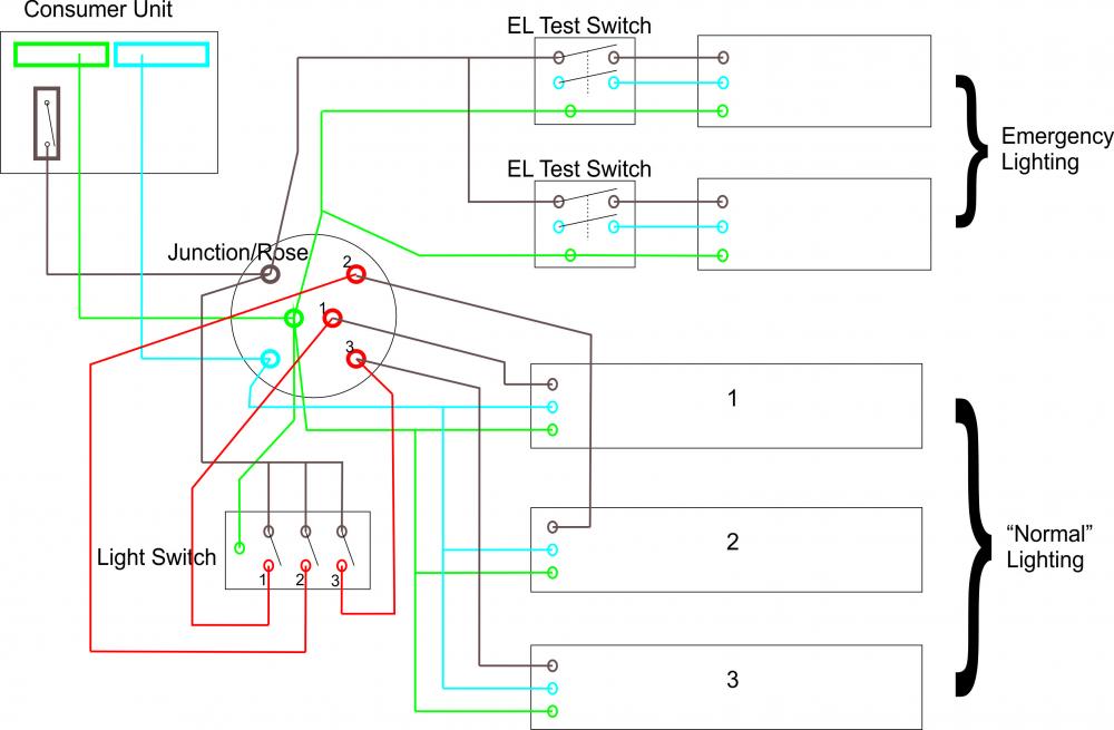
Self Test Emergency Lighting Wiring Diagram

Rj11 Socket Wiring Diagram Australia, How to punch down an RJ11 Telephone Jack, 6.36 MB, 04:38, 387,634, CableSupply.com, 2009-08-05T00:16:07.000000Z, 19, Rj11 Socket Wiring Diagram Australia | Computacion, Redes de computadoras, Computadoras, www.pinterest.com.mx, 728 x 783, jpeg, rj11 wiring rj45 diagram cable ethernet usb jack pinout adapter cat5 female male convert using rs485 cat wires code socket, 20, rj11-socket-wiring-diagram-australia, Anime Arts
Hole and install switch as sho (see illustration 1 & 2) to test emergency operation, ensure emergency source is connected and red led is illuminated. Instruction sheet 93005933 rev a 9/06. If emergency lights do not stay on for at least 2. 5 seconds, confirm wiring connections and perform testing
Emergency light switch wiring diagram you emergency lighting standards cibse journal emergency lighting testing preventing emergency light or exit sign failure batteries bulbs more Ul924 qualified emergency led drivers detect the loss of power and switch control to battery power in emergency conditions. The diagram below illustrates the typical em battery backup system. The detailed wiring diagram below illustrates that the emergency led driver powers the led load using the ac led driver input, in normal power mode, and with. Self test emergency lighting explained. This technology is in compliance with bs5266. A function test is a 30 second test that simulates a mains failure and checks the operation of the emergency light source from the battery supply. The local indicator led fast flashes green whilst the function test is in progress. If there is a failure during a function test the local indicator led either changes to a permanent.
Wiring up/Testing of Emergency Lighting - Emergency Lighting - Safelincs Fire Safety Forum

Emergency Lighting products - DALI and Self-Test functionality

ONELUX Sock Self test Emergency conversion kit for LED lighting 9~55VDC inc battery | GHS
Poselco Lighting Blog

Emergency and exit lighting – Energy Safe Victoria
The Newest Led Tube Emergency Light Conversion Kit For Led Tube Linear Self Test Emergency

50 Luxury Emergency Light Wiring Diagram in 2020 | Emergency lighting, Diagram, Emergency

Emergency Test Switch Installation - Ektor UK
Emergency Light Wiring Diagram Up - Wiring Diagram & Schemas
emergency light switch wiring diagram! - YouTube
